55/58 Chevy Truck Project.
 Fully Engaged
Posts: 211
Joined: Thu Jul 28, 2011 1:30 pm Location: Inglewood, CA Country: USA |
I'm going to take a pic for you, as soon as I can.
|
 Board Moderator
Posts: 9890
Joined: Fri Oct 20, 2006 12:40 pm Location: ARIZONA |
Great. Thank you.
1968 Coronet R/T
ACTS 16:31 |
Fully Engaged
Posts: 211
Joined: Thu Jul 28, 2011 1:30 pm Location: Inglewood, CA Country: USA |
I done you one better. I posted pics of the truck I looked at when I was having problems with my flip kit.. Since my truck is not together anymore I thought this was a better option.
|
Board Moderator
Posts: 9890
Joined: Fri Oct 20, 2006 12:40 pm Location: ARIZONA |
I think I see the problem. Thank you very much for your help.
1968 Coronet R/T
ACTS 16:31 |
Board Moderator
Posts: 9890
Joined: Fri Oct 20, 2006 12:40 pm Location: ARIZONA |
Got it to close. Took 4 hours trying to adjust the gaps and still don't like them but that's what you get when you take on a project someone else started. The hood is definitely tweaked and I had to do a little "persuading" to get it to sit and close right.
I'll update my post in a day or so with some picks. Thanks again for your help. 1968 Coronet R/T
ACTS 16:31 |
Fully Engaged
Posts: 211
Joined: Thu Jul 28, 2011 1:30 pm Location: Inglewood, CA Country: USA |
You are welcome buddy and please do post pics when you get it to your liking.
|
|
Top Contributor
Posts: 6233
Joined: Tue Sep 16, 2008 1:17 pm Location: Pahrump NV. Country: USA |
Bam
I was talking more about the trany mount itself and setting the transmision and engine angle up correctly with the engine mounts, how to set the angle between transmission tail shaft angle to third member pinion angle. something along the lines of 4 degrees negative on the trans and 3 degrees positive on the Pinion. may be different angles on a truck than a car I don't know? The guy I helped we leveled the engine side to side off carb mount on the engine intake manifold and just leveled the transmission with a level off the bottom of the transmission pan it seamed a bit crude to me and I never did see truck run or drive so I don't know if it worked or not. I'm sure it did but was it the right way to do it I don't know? he wasn't even concerned with the drive shaft angles and I know its important so the u joints don't rattle. Dennis B.
A&P Mechanic, FCC General radio Telephone Operator Line Maintenance A&P Mechanic and MOC Tech specialist. |
Fully Engaged
Posts: 211
Joined: Thu Jul 28, 2011 1:30 pm Location: Inglewood, CA Country: USA |
I've always strive for a pinion angle 1-3 degrees in a parallel relationship between the trans and the rearend. But theoretically the pinion angle is fine as long as they are parallel. Like if the trans is pointed down 4 degrees the rear should be pointed up 4 degrees. When measuring the pinion angle I put angle protractor on the trans tail shaft to find that angle and on the rearend flange to find its angle.
|
Fully Engaged
Posts: 211
Joined: Thu Jul 28, 2011 1:30 pm Location: Inglewood, CA Country: USA |
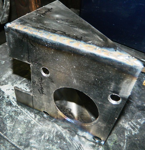
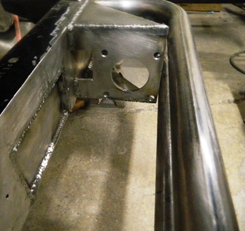
The set back of installing the x member means I can no longer use the factory brake assembly. So here is my brake bracket I fabricated. As you can see I also had to notch the frame to have clearance for the Hydroboost unit.
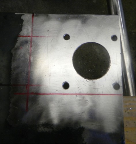 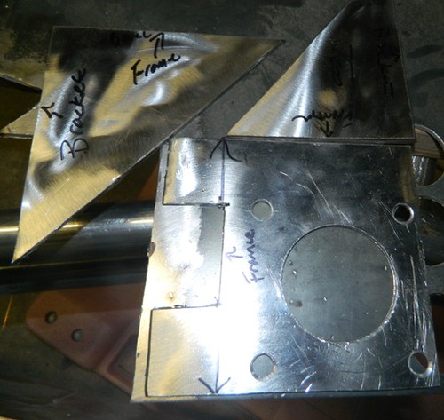   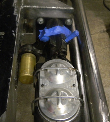 I already modified the panel assembly, all that is required is a push rod extension but I think I better wait until the cab is back on to mock it up so that I know the brake is in the right spot. |
Fully Engaged
Posts: 211
Joined: Thu Jul 28, 2011 1:30 pm Location: Inglewood, CA Country: USA |
Here is the piece I fabricated for the pedal assembly.
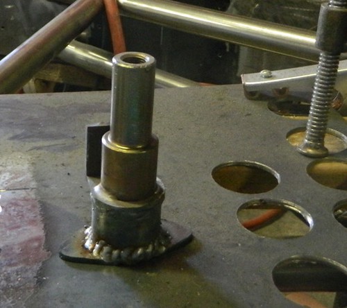 After a lot of measuring here it is tacked in place. I'm going to leave it tacked until the cab is back on the frame, because I may have to move it a little bit. 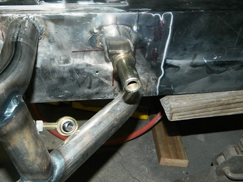 Here is the pedal installed. Yes the push rod connection clears the bottom tube by about 1/2 inch. As you can see I need to make or purchase a longer push rod extension. 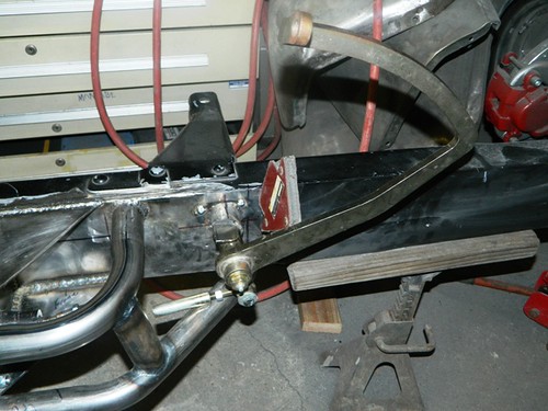 |
Return to Completed & In Progress Member Projects
Who is online
Users browsing this forum: No registered users and 70 guests
Powered by phpBB© 2000, 2002, 2005, 2007 phpBB Group
Advertisements by Advertisement Management