Ultimate Compressed Air Dryer

Any questions about tools or supplies. Post your compressor/gun questions here.

User avatar

Fully Engaged
Posts: 355
Joined: Sun Aug 17, 2014 6:04 pm
Location: Gulf Breeze, FL, USA
Country:
USA
PostPosted: Fri Oct 31, 2014 8:09 am
This project just sort of snowballed. I'm in the process of repainting my Tundra. Before I even started, I knew I had to do something to upgrade my shop compressed air system. I originally had a Kobalt 1.8 HP/30 gallon compressor and a single inline water/oil separator. It is adequate for painting cabinet doors and other small projects. However, during very hot and humid months down here in NW Florida, I'd sometimes have water coming out of the spray gun or other air tools.

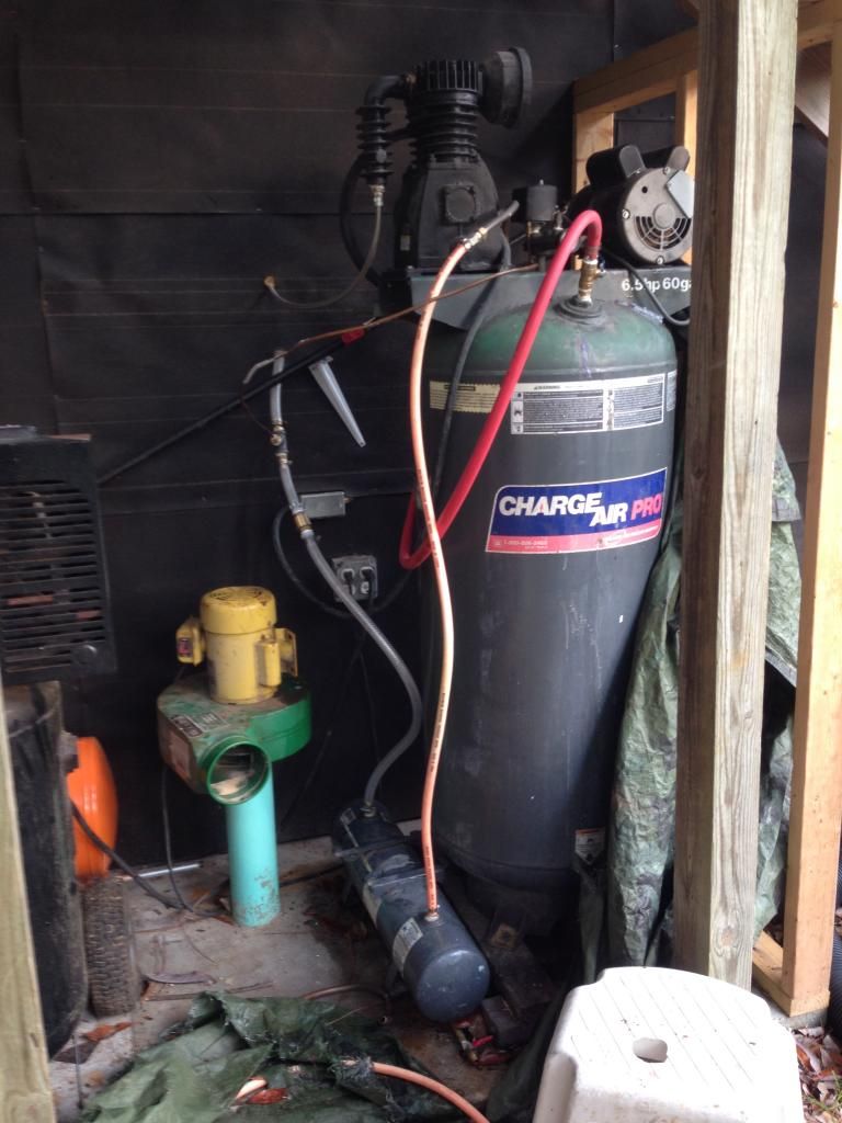
I started searching craigslist for larger compressor, one that could supply adequate air to a spray gun my itself. I found one that I thought was a 6.5HP/60 gallon. It was labeled as such. I paid $350 for it. When I got it home, I realized it had a new Harbor Freight 3 HP compressor and motor. Good that they're new. Bad that it is still inadequate.

So, I needed to address the moisture in the system and somehow connect both compressors together so I'd have 4.8 HP and 90 gallons. The recommended minimum HP for autobody work is 5 HP. I'm close.

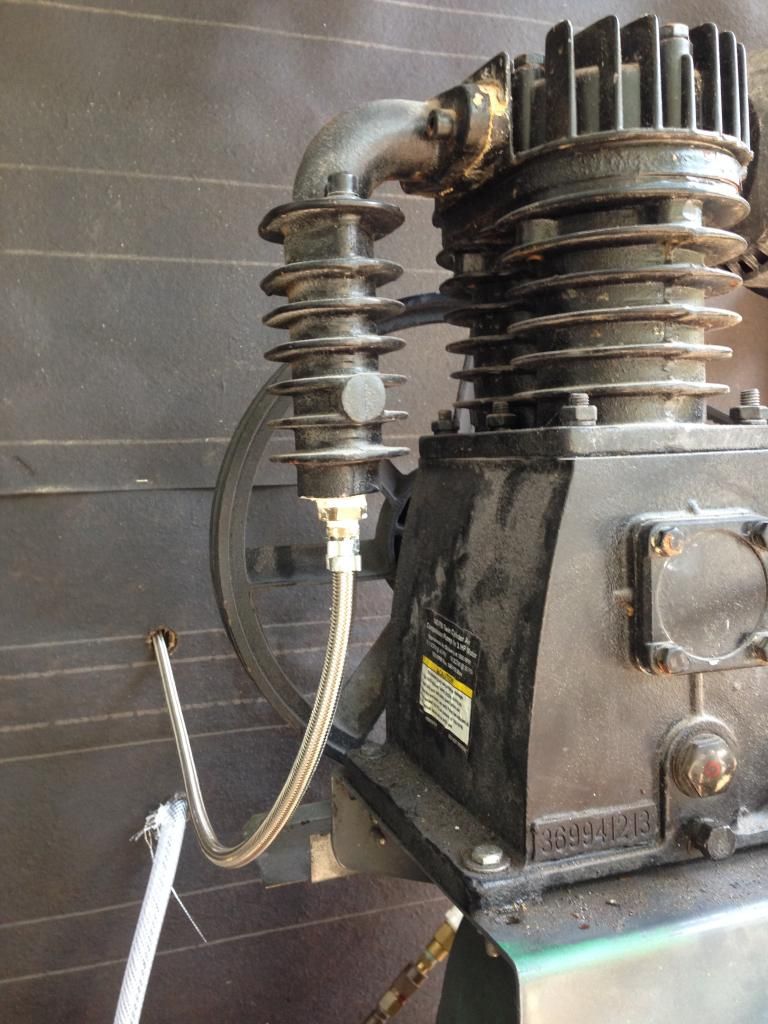
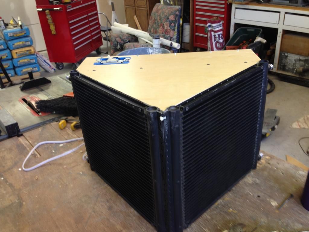
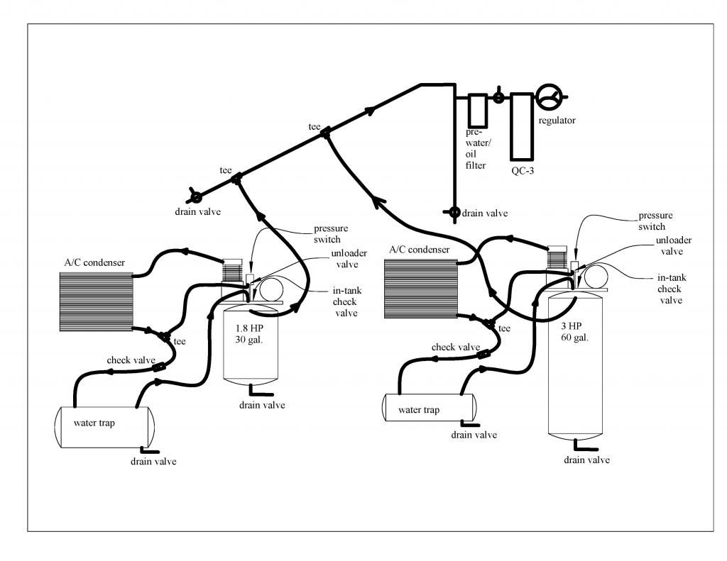
Here's the schematic for the completed system. I took the output of each compressor directly to an a/c condenser via a teflon braided hose. The air coming out of the compressor head is very hot, and I was worried about melting a rubber hose. I bought the brand new, universal a/c condensers off eBay for $40 each. I picked up the braided hose at a local rubber specialties shop, and the fittings off the O'Reilly auto parts website. I believe they are a No. 6 and No. 8 fitting, but the size is condenser specific. I suggest that you have the hose people make up the braided hoses. It was a **** getting the fittings into the braided hose. I had to sand off most of the barb from the brass hose barbs because the 3/8" teflon braided hose isn't really that. It is smaller. This was the hardest part of the whole project. Just let them do it.

From the a/c condenser, the cooled air goes into another tank that acts as a water trap. The temperature drop is 100-120 degrees F. I can see water streaming down the clear hose into the water trap. The water stays in the tank, and the dry air goes back into the main tank.

I had to add an inline check valve between the condenser and water trap, and a tee fitting upstream that connects to the unloader valve. With the unloader valve connect to the in-tank check valve, the entire system had to leak down, which took forever. I was worried the compressor would try to kick-in before the compressor head unloaded adequately.

I built a fan enclosure for the condensers and mounted them inside my workshop. During the summer months, I air condition my workshop, so the cooler air will make the condensers more efficient.

The output of each compressor goes into a sloped iron pipe that goes through the wall into my workshop, then through a pre-water/oil separator and then into the QC-3 desiccant. filter then a regulator.
Image
We hold these truths to be self-evident, that all men are created equal, that they are endowed by their Creator with certain unalienable Rights, that among these are Life, Liberty and the pursuit of Happiness.

User avatar

Fully Engaged
Posts: 355
Joined: Sun Aug 17, 2014 6:04 pm
Location: Gulf Breeze, FL, USA
Country:
USA
PostPosted: Fri Oct 31, 2014 8:23 am
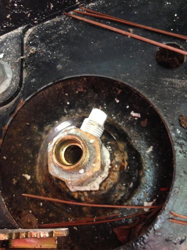
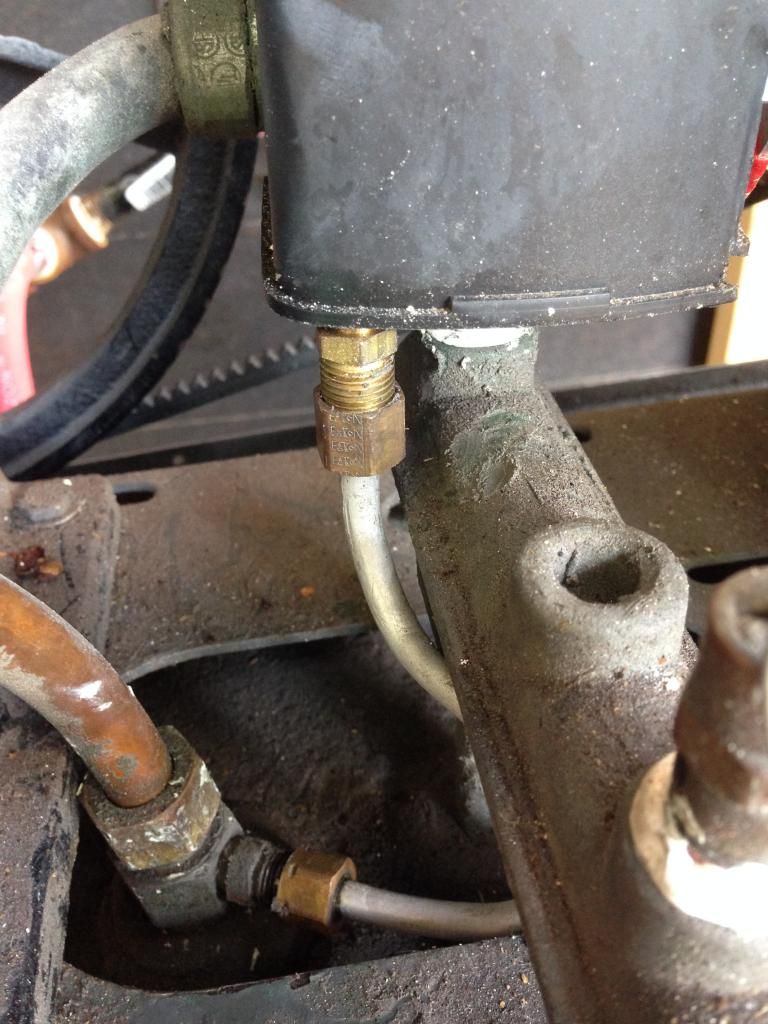
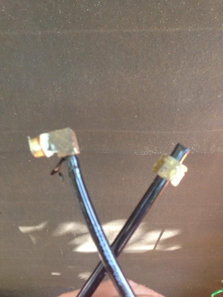
This is what I disconnected from my 1.8 HP. One end went to the in-tank check valve and the other to the unloader valve. I plugged the hole in the check valve. I did the same on my 3 HP.

Image


Image


Removed this tube and plugged the in-tank check valve.

Image
We hold these truths to be self-evident, that all men are created equal, that they are endowed by their Creator with certain unalienable Rights, that among these are Life, Liberty and the pursuit of Happiness.

User avatar

Fully Engaged
Posts: 355
Joined: Sun Aug 17, 2014 6:04 pm
Location: Gulf Breeze, FL, USA
Country:
USA
PostPosted: Fri Oct 31, 2014 8:33 am
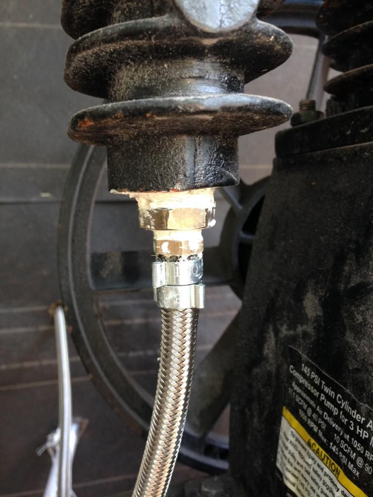
This braided teflon hose has performed well, even though I had to remove most of the barbs to get the brass fitting in. I had to heat the end of the hose with a heat gun, stetch the opening with a needle nose pliers, then hammer the fitting in with a deadblow hammer. Several times the end of the fitting would catch the teflon and tear it, so I had to redo the first one a couple of times before I got it right. I ultimately rounded over the end of the barb with my bench top belt sander so it would not catch. If you look down the end of the barb and do not see any curled up teflon, then it's good to go. I used two crimp hose clamps on each end to make sure the hose didn't pop off.

Image


Image
We hold these truths to be self-evident, that all men are created equal, that they are endowed by their Creator with certain unalienable Rights, that among these are Life, Liberty and the pursuit of Happiness.

User avatar

Fully Engaged
Posts: 355
Joined: Sun Aug 17, 2014 6:04 pm
Location: Gulf Breeze, FL, USA
Country:
USA
PostPosted: Fri Oct 31, 2014 8:49 am
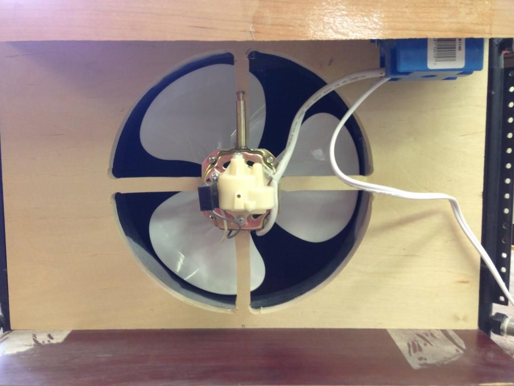
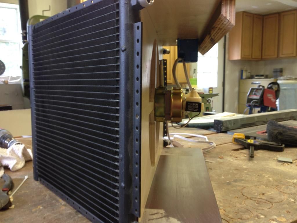
Here is the fan box I made for the two condensers. It's just scrap plywood I had laying around. The fan is a small oscillating fan I bought at Lowes for $15. I just need the motor and blades. It has decent airflow and does the trick.

Image


Image


Notice the cleat at the top rear of the box. The other half of this 45 degree rip is screwed to the wall. This makes it easy to hang the box and remove it if needed.

Image


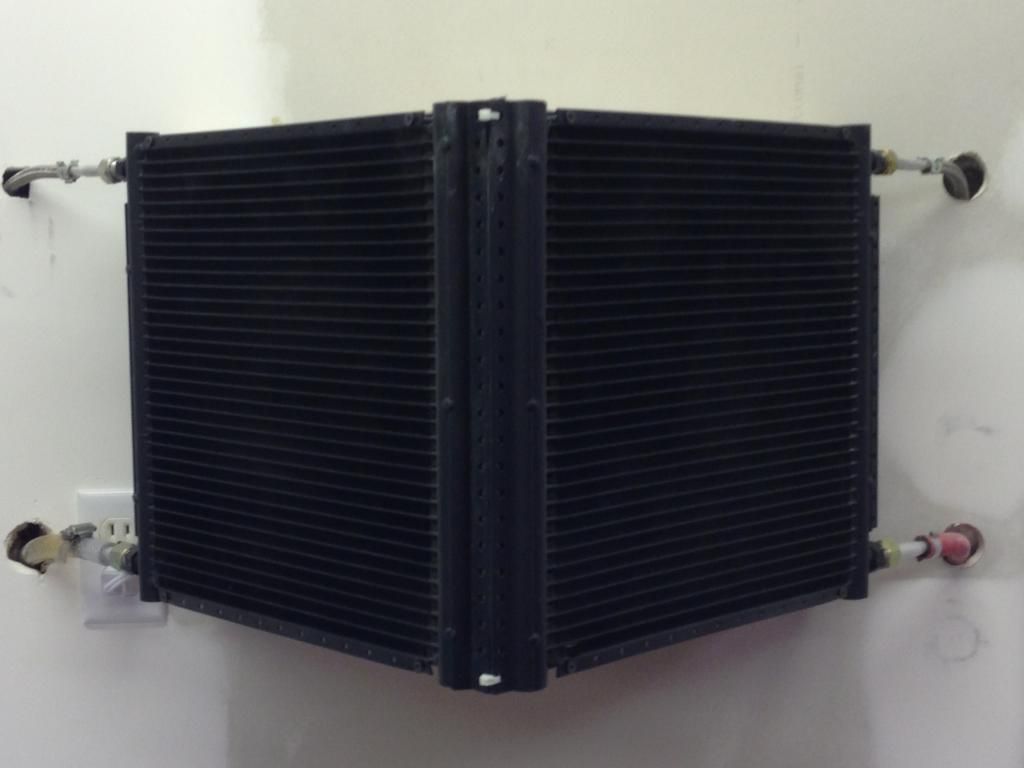
Here it is hanging on the wall. I tidied up the hoses, so I had some holes in the drywall to patch. Two things I'm going to do next: install some escutcheon rings around the hoses, and add a relay so that the fan comes on automatically when either one of the compressors is running.

Image
We hold these truths to be self-evident, that all men are created equal, that they are endowed by their Creator with certain unalienable Rights, that among these are Life, Liberty and the pursuit of Happiness.

User avatar

Fully Engaged
Posts: 355
Joined: Sun Aug 17, 2014 6:04 pm
Location: Gulf Breeze, FL, USA
Country:
USA
PostPosted: Fri Oct 31, 2014 8:58 am
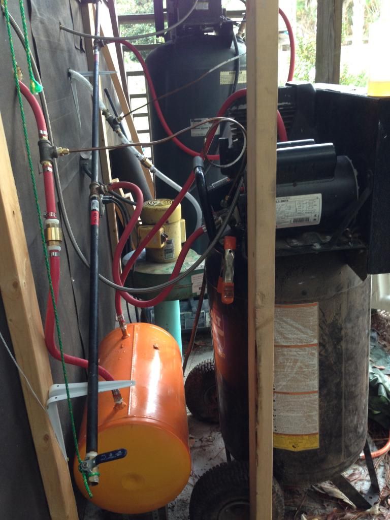
In this picture, you can see pretty much everything. For the 1.8 HP side, the air goes from the condenser past a tee, through a check valve, then into the orange tank, which is the water trap. I bought if from Harbor Freight, but had to weld in my own nipples using my MIG welder. From the water trap, the air goes back into the main tank. The tank is connected the the sloped iron pipe with a tee fitting.

Image


On the 3 HP side, it's the same set up. This water trap is the tank from my last hotdog compressor. I'm glad I saved it. I was going to use it to make a homemade coffee bean roaster, but I got to this project first.

Image
We hold these truths to be self-evident, that all men are created equal, that they are endowed by their Creator with certain unalienable Rights, that among these are Life, Liberty and the pursuit of Happiness.

User avatar

Fully Engaged
Posts: 355
Joined: Sun Aug 17, 2014 6:04 pm
Location: Gulf Breeze, FL, USA
Country:
USA
PostPosted: Fri Oct 31, 2014 9:22 am
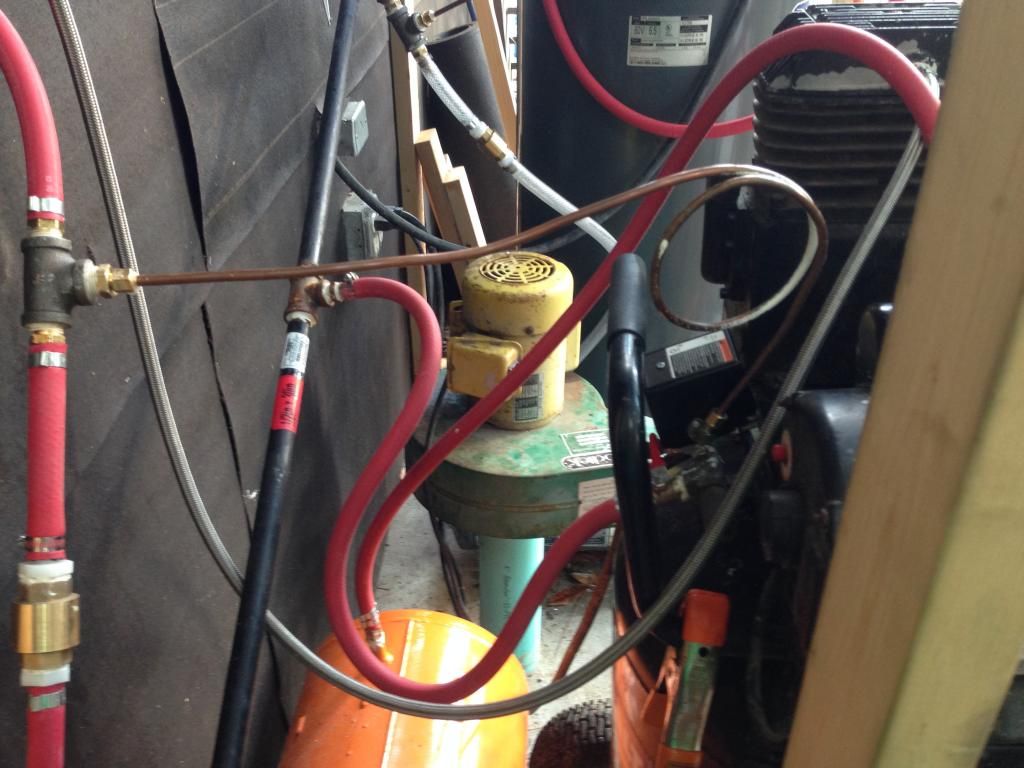
Figuring out the check valve and unloader valve setup took some research, but I finally got a clue. The unloader valves are actuated by the pressure switches. They really have nothing to do with the in-tank check valves as far as how they work. They just open up and bleed the air off between the check valve and compressor head. The reason is that if air pressure remained on the cylinder, the motor couldn't turn it. You'd smoke your belt.

I wanted to keep the water traps pressurized, but bleed off the air pressure from the a/c condenser, braided hose, and compressor head. The reason I decided to bleed off the condensers is because I'd have to add a tee fitting to the braided hose. Did I mention how hard that is? :knockout:

The inline check valve ($5 ebay, made in USA) keeps the air in the water traps, and via the tee fitting and length of 1/4" copper tubing, the unloader valve bleeds everything upstream of the check valve. Before I installed this, it took about 5 minutes for all this to bleed off. Now, it takes just a couple of seconds.

Image


If you're going to use the crimp style hose clamps to put together your sections of hoses, made sure that at least one end of each hose is secured with a screw type hose clamp. You will have leaks, and you will have to disassemble and reassemble stuff before everything is leak-free. I used Blue Monster pipe thread sealant. It worked well. The only thing that gave me trouble were the nylon barbs that are in each end of the check valves. After assembling and reassembling those a couple of times, I finally had to use teflon tape on the barb threads, and sealant on the check valve threads. The only other leaks I have is a very tiny one where the copper pipe goes into the unloader valve. This doesn't matter. The copper pipe is bled down each cycle and the air loss is insignificant. I just didn't want to damage the unloader valve.
We hold these truths to be self-evident, that all men are created equal, that they are endowed by their Creator with certain unalienable Rights, that among these are Life, Liberty and the pursuit of Happiness.

User avatar

Fully Engaged
Posts: 355
Joined: Sun Aug 17, 2014 6:04 pm
Location: Gulf Breeze, FL, USA
Country:
USA
PostPosted: Fri Oct 31, 2014 9:37 am
The last step is to adjust your pressure switches for cut-in and cut-out pressures, and differential setting if you pressure switch has that adjustment.

Here is a good video that explains how to adjust them.
https://www.youtube.com/watch?v=zh_hfD3rCA0
For my Kobalt 1.8 HP, my pressure switch is preset at the factory for a 30 psi differential between cut-in and cut-out. It cuts in at 125 and cuts out at 155. That was too high for me. I think my welds on the water trap tank are good. Had that nice sizzle going while I made C-shaped loops molten metal around the circumference of the steel nipple, but I'd rather not do a test-to-failure on it.

I had to by a tamper proof torx set, but I was able to back it down to 106/126. The differential is fine I think, but I can decrease the differential if needed. In other words, I could use the differential adjustment screw to make it cut-in at 116 and cut-out at 126, instead of 106.

The Square D switch on my big compressor only had an adjustment for cut-in/cut-out. Differential is preset and not adjustable. They both kick in and out at about the same time. I set the large one to kick in first, then the smaller one a few moments later.

This was a little confusing at first, but now I fully understand it.

I did a test by hooking up my primer gun and wired the trigger open. I let it spray wide open for a very long time, much longer than it would take me to go around my truck. Both compressors cut in, but the pressure remained steady at 100 psi for the entire time. Also, the air coming out was completely dry.
We hold these truths to be self-evident, that all men are created equal, that they are endowed by their Creator with certain unalienable Rights, that among these are Life, Liberty and the pursuit of Happiness.

User avatar

Fully Engaged
Posts: 355
Joined: Sun Aug 17, 2014 6:04 pm
Location: Gulf Breeze, FL, USA
Country:
USA
PostPosted: Fri Oct 31, 2014 9:43 am
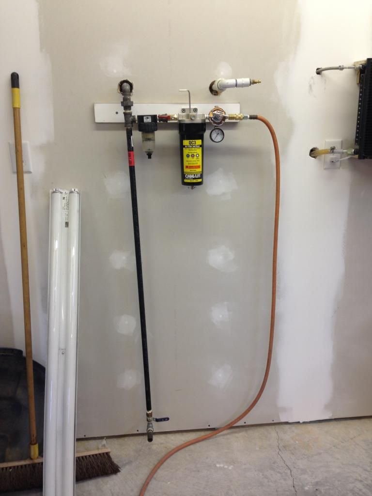
Here's my filter and regulator setup. The prefilter was from my old system. Figured it couldn't hurt to use it.

I don't need the QC-3 desiccant dryer when I run air tools, so I bypass it with the quick disconnect at the bottom of the drain pipe. I'm going to get a tee and short nipple and add that just below the existing tee on the drain pipe. That way I can drain the pipe without having to remove the quick disconnect. I seriously doubt that there will be any moisture to drain out, but it's nice to have the ability.

I ran my DA sander for hours one day with the QC-3 bypassed, and I didn't get a single droplet of air. The QC-3 is probably overkill, but with all the hard prep work I'm putting into my truck, the last thing I want is to have a pad paint job in the end.

Image
We hold these truths to be self-evident, that all men are created equal, that they are endowed by their Creator with certain unalienable Rights, that among these are Life, Liberty and the pursuit of Happiness.

User avatar

No Turning Back
Posts: 527
Joined: Tue May 08, 2012 6:53 pm

Country:
USA
PostPosted: Sat Nov 01, 2014 5:35 am
Understatement of the year...
"This project just sort of snowballed"

:shocked: :worthy:

My setup: 60 gallon comp, drain tank before spraying, 100' air hose, and a new one of these for finish coats

Image


:wink: :bighug:

User avatar

Fully Engaged
Posts: 355
Joined: Sun Aug 17, 2014 6:04 pm
Location: Gulf Breeze, FL, USA
Country:
USA
PostPosted: Sat Nov 01, 2014 7:14 am
NOVAFREEK6872 wrote:Understatement of the year...
"This project just sort of snowballed"

:shocked: :worthy:

My setup: 60 gallon comp, drain tank before spraying, 100' air hose, and a new one of these for finish coats

Image


:wink: :bighug:


I don't think my 3HP/60 gallon compressor would hack it, so the tandem set up was inevitable. The dryer part? I was on a mission! :happy:
We hold these truths to be self-evident, that all men are created equal, that they are endowed by their Creator with certain unalienable Rights, that among these are Life, Liberty and the pursuit of Happiness.
Next

Return to Tools and Supplies

Who is online

Users browsing this forum: No registered users and 33 guests